
HDF Cover Type Freeze Dryer Models
Review the process, equipment duties and project boundary from one defined basis.
Confirm the Product and Batch Route Before Comparing Shelf Area
Choose the operating family first
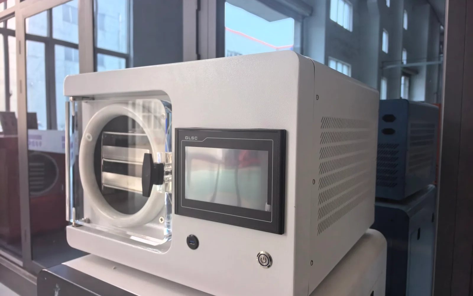
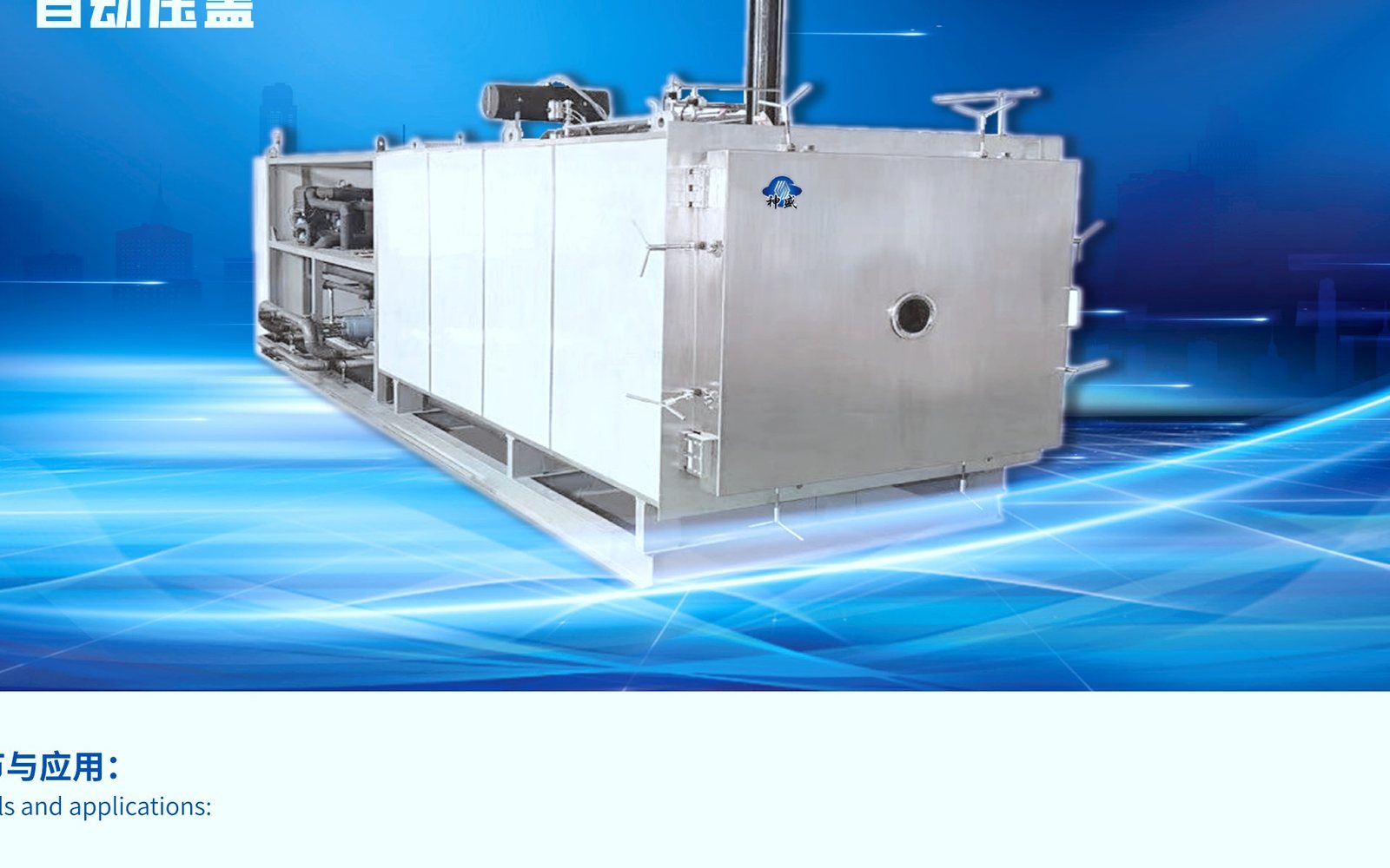
A capping freeze dryer combines drying with a controlled closure step, so the product and the vial route are specified together. Record the vial size, the fill volume, the stopper type and whether the product must be stoppered under vacuum or in a controlled gas atmosphere. The capping step is not an accessory; it determines the shelf travel, the pressure control and the sealing sequence.
Confirm the finished container condition before comparing capacity. A vial that must be stoppered at a defined chamber pressure and then sealed without moisture uptake needs the shelf, the stoppering mechanism and the gas backfill to be designed as one system. The same shelf area produces very different results if the closure route is an afterthought.
For this capping application, the comparison only becomes meaningful once the stoppering and sealing sequence are written down, because those are the results the shelf area must actually deliver.
If the written basis changes, restart the comparison from that new basis instead of carrying an earlier shelf-area figure forward.
Restart the comparison from the written basis whenever it changes, and the shelf-area figure will stay honest.
The stoppering sequence is part of that basis, not an accessory to it.
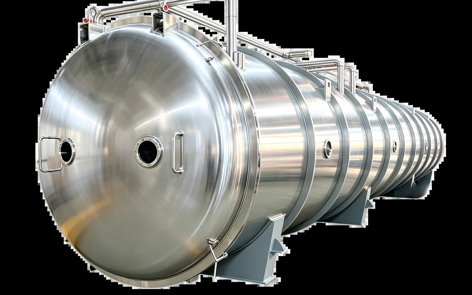
Size the Complete Batch Route, Not the Chamber Alone
Freeze-drying duty and parameter consequences
Size the batch around the vials and the closure cycle, not the chamber alone. Count the vials per shelf, the fill depth and the stopper movement, then check that the condenser can remove the water from that load within the cycle time. The capping mechanism and the gas backfill add process steps that must fit inside the batch rhythm.
Include the sealing and inspection handoff in the batch plan. After drying and stoppering, the vials must be sealed, inspected and labelled without breaking sterility or letting moisture back in, so the dryer's batch size should match the downstream sealing capacity rather than the theoretical shelf area.
Count the turnaround between cycles in the batch plan: unloading, defrosting, cleaning and reloading all consume time, and the daily output is set by the whole route rather than by the shelves in isolation.
For this capping machine, the batch calculation is complete only when the stoppering and sealing sequence are included alongside the shelf area.
Include the turnaround and the the stoppering and sealing sequence in the batch calculation, or the daily output will look better on paper than it is.
Include the sealing step in the batch rhythm, or the shelf area will overstate the output.
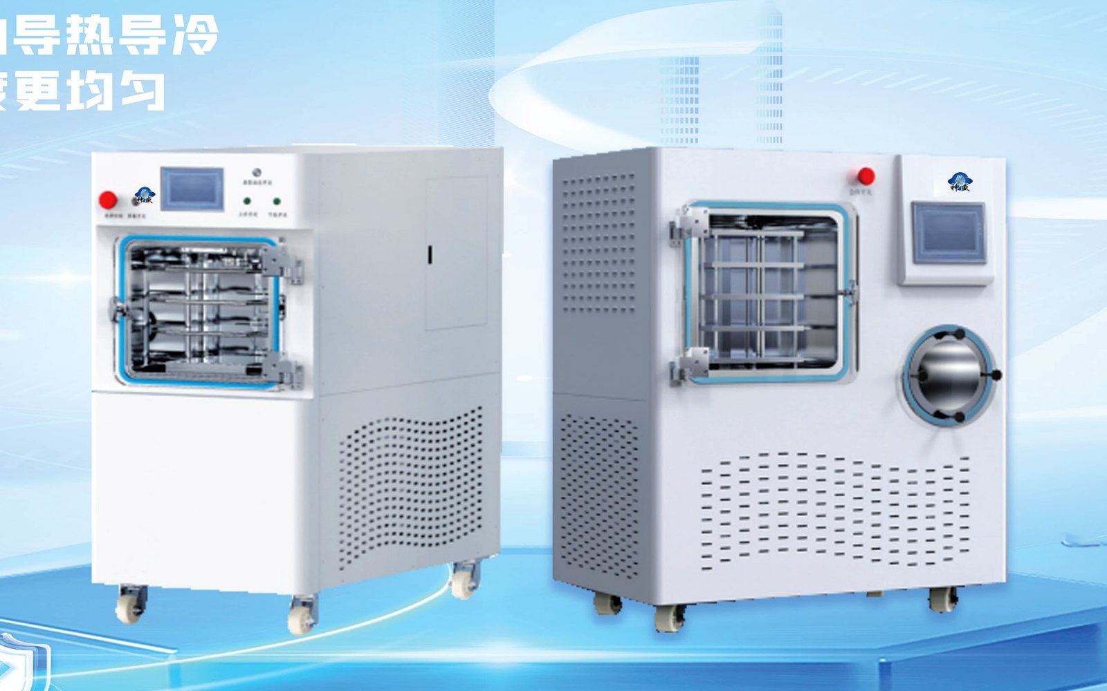
Keep the Family, Model and Operating Duty Together
Models and technical parameters
Keep the shelf area, the condenser and the cycle recipe in one view. Shelf area sets how much product can be loaded, but the condenser must remove the water that sublimes from that load, and the vacuum and refrigeration systems must hold the chamber at the setpoint while it happens. Quoting one of these numbers in isolation produces a machine that looks right on a data sheet and stalls in operation.
The HDF capping freeze dryer is read as a documented starting configuration, not as a fixed answer. Its published shelf area, tray count and condenser rating describe a reference load; the operating duty for your product is established by reconciling the load weight, the fill depth, the freezing point and the final moisture target into one cycle. When the family, the model and the duty travel together, the quotation matches the process instead of the photograph.
Where the published figure is only a reference, say so in the review and carry the product-specific duty forward instead, so the selected model is defended by evidence rather than by a brochure number.
That discipline is what keeps a catalog number from quietly turning into a performance commitment.
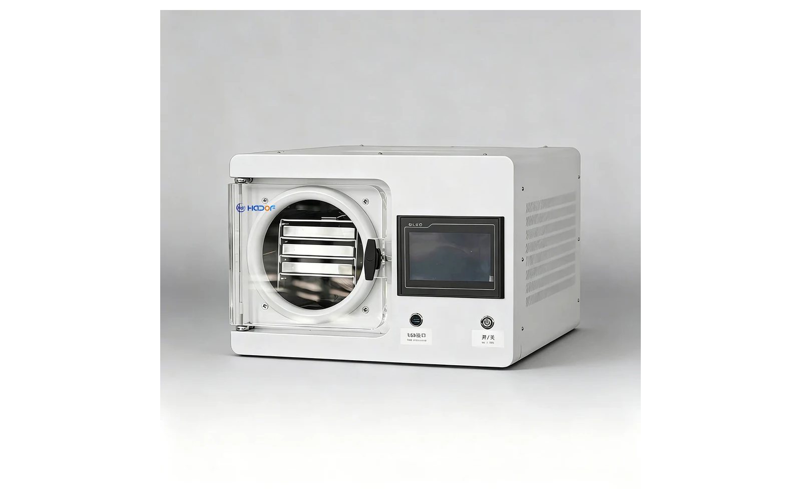
Resolve Four Connected Decisions Before Quotation
Selection logic and configuration boundary
- 01 / ProductDefine product state and the accepted endpoint.Record initial water or moisture basis, dimensions, loading depth, sensitivity, finished requirement and measurement method.
- 02 / BatchConvert production demand into useful loading and cycles.Separate batch mass, shelf area, water per batch, cycle allowance, defrost, cleaning and turnaround.
- 03 / ArchitectureConnect freezing, shelves, condenser and vacuum duty.Confirm pre-freezing route, shelf execution, condenser loading, vacuum system, refrigeration and control evidence.
- 04 / InterfaceClose factory, handling and pack-out boundaries.Review utilities, room and access, loading, unloading, cleaning, data, downstream protection and responsible parties.
Four connected decisions should be resolved before a quotation is meaningful. First, the shelf and tray configuration, because the tray spacing, the product depth and the loading method set the effective shelf area. Second, the condenser and vacuum package, which must remove the sublimed water without allowing the chamber pressure to drift. Third, the control and data system, including recipe storage, cycle logging and alarms. Fourth, loading, unloading and cleaning, which decide the labour and the downtime between cycles.
These four decisions are not independent. A deeper product load slows the cycle and increases the water the condenser must catch; a sealed or capping application adds an aseptic or sealing step that changes the shelf design; a research unit adds data export and ramp control that a production machine does not need. Work through them for the HDF capping freeze dryer with the actual product before comparing prices, so the quotation includes the capability that makes the machine usable.
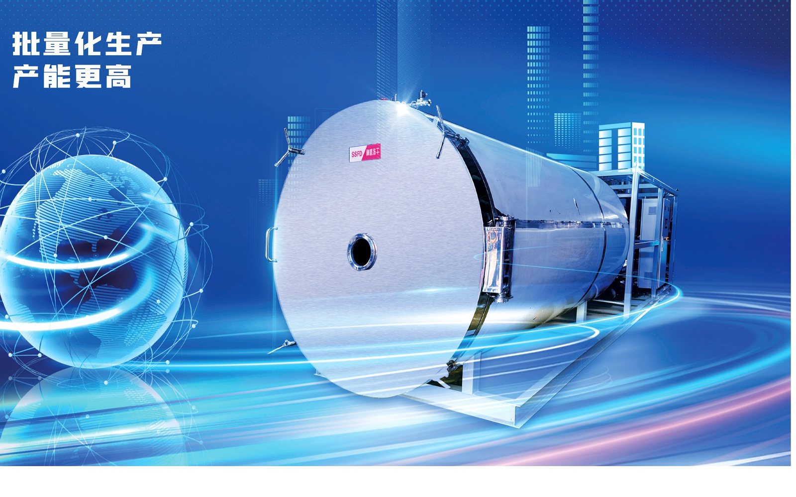
Turn the Catalog Row Into a Testable Project Record
Quality, testing, evidence and acceptance
The acceptance plan should state which catalog values are inspected, which functions are demonstrated, which product measurements are available at the factory and which checks can occur only after installation.
Model row, shelf and condenser data, utilities, layout, options, responsibilities and selected evidence.
Identity, construction, controls, safety, vacuum and refrigeration functions, dry run and agreed records.
Test material, batch load, freezing history, loading depth, cycle record, endpoint and declared limits.
Installation, utilities, product run, recipes, operator tasks, cleaning, pack-out and closure of open items.
Turn the catalog row into a testable record by writing the product, the load weight, the shelf temperature, the chamber pressure and the final moisture target into an acceptance plan. A freeze dryer is validated by its cycle data: the product temperature, the chamber pressure and the condenser load over time. Agree how that data is recorded and what it must show before the machine is accepted.
Run the trial on the HDF capping freeze dryer with representative product and keep the cycle record. Confirm the freezing stage reaches the target, the primary drying completes without melting the product, and the final moisture meets the specification. The same cycle record is the evidence you will show a customer or an auditor, so it must be kept with the machine documentation rather than treated as a one-off demonstration.
Confirm Responsibilities Beyond the Machine Name
Quotation, delivery and support scope
Cover type HDF-FD series
Select a model to inspect its dimensions, duty and utilities. Compare values within the same family and operating basis.
| Area | 1 m² |
|---|---|
| Envelope L×W×H | 3000×1000×2700 mm |
| Power | 11 kW |
| Plates | 4+1 |
| Cold trap | -50 to -80 °C |
| Shelf temperature | -45 to +70 °C |
| Vacuum | ≤5 Pa |
| Loading | 10 kg |
| Water capture | 20 kg |
| Cooling | Air |
| Heating | Silicone oil |
| Area | 2 m² |
|---|---|
| Envelope L×W×H | 4250×1330×3200 mm |
| Power | 20 kW |
| Plates | 4+1 |
| Cold trap | -50 to -80 °C |
| Shelf temperature | -45 to +70 °C |
| Vacuum | ≤5 Pa |
| Loading | 20 kg |
| Water capture | 40 kg |
| Cooling | Air |
| Heating | Silicone oil |
| Area | 3 m² |
|---|---|
| Envelope L×W×H | 4280×1330×3400 mm |
| Power | 26 kW |
| Plates | 6+1 |
| Cold trap | -50 to -80 °C |
| Shelf temperature | -45 to +70 °C |
| Vacuum | ≤5 Pa |
| Loading | 30 kg |
| Water capture | 60 kg |
| Cooling | Air |
| Heating | Silicone oil |
| Area | 5 m² |
|---|---|
| Envelope L×W×H | 4800×1640×3300 mm |
| Power | 38 kW |
| Plates | 5+1 |
| Cold trap | -50 to -80 °C |
| Shelf temperature | -45 to +70 °C |
| Vacuum | ≤5 Pa |
| Loading | 50 kg |
| Water capture | 100 kg |
| Cooling | Water |
| Heating | Silicone oil |
| Area | 7.5 m² |
|---|---|
| Envelope L×W×H | 5100×1640×2400 mm |
| Power | 48 kW |
| Plates | 7+1 |
| Cold trap | -50 to -80 °C |
| Shelf temperature | -45 to +70 °C |
| Vacuum | ≤5 Pa |
| Loading | 75 kg |
| Water capture | 150 kg |
| Cooling | Water |
| Heating | Silicone oil |
| Area | 10 m² |
|---|---|
| Envelope L×W×H | 5500×1640×4000 mm |
| Power | 59 kW |
| Plates | 9+1 |
| Cold trap | -50 to -80 °C |
| Shelf temperature | -45 to +70 °C |
| Vacuum | ≤5 Pa |
| Loading | 100 kg |
| Water capture | 200 kg |
| Cooling | Water |
| Heating | Silicone oil |
| Area | 13 m² |
|---|---|
| Envelope L×W×H | 5500×1940×4000 mm |
| Power | 75 kW |
| Plates | 9+1 |
| Cold trap | -50 to -80 °C |
| Shelf temperature | -45 to +70 °C |
| Vacuum | ≤5 Pa |
| Loading | 130 kg |
| Water capture | 260 kg |
| Cooling | Water |
| Heating | Silicone oil |
| Area | 15 m² |
|---|---|
| Envelope L×W×H | 5500×1940×4000 mm |
| Power | 78 kW |
| Plates | 10+1 |
| Cold trap | -50 to -80 °C |
| Shelf temperature | -45 to +70 °C |
| Vacuum | ≤5 Pa |
| Loading | 150 kg |
| Water capture | 300 kg |
| Cooling | Water |
| Heating | Silicone oil |
| Area | 20 m² |
|---|---|
| Envelope L×W×H | 6800×1980×4400 mm |
| Power | 100 kW |
| Plates | 11+1 |
| Cold trap | -50 to -80 °C |
| Shelf temperature | -45 to +70 °C |
| Vacuum | ≤10 Pa |
| Loading | 200 kg |
| Water capture | 400 kg |
| Cooling | Water |
| Heating | Silicone oil |
| Area | 25 m² |
|---|---|
| Envelope L×W×H | 7000×2420×4600 mm |
| Power | 120 kW |
| Plates | 11+1 |
| Cold trap | -50 to -80 °C |
| Shelf temperature | -45 to +70 °C |
| Vacuum | ≤10 Pa |
| Loading | 250 kg |
| Water capture | 500 kg |
| Cooling | Water |
| Heating | Silicone oil |
| Area | 30 m² |
|---|---|
| Envelope L×W×H | 7500×2420×4600 mm |
| Power | 140 kW |
| Plates | 11+1 |
| Cold trap | -50 to -80 °C |
| Shelf temperature | -45 to +70 °C |
| Vacuum | ≤10 Pa |
| Loading | 300 kg |
| Water capture | 600 kg |
| Cooling | Water |
| Heating | Silicone oil |
| Area | 40 m² |
|---|---|
| Envelope L×W×H | 9200×2660×4750 mm |
| Power | 200 kW |
| Plates | 14+1 |
| Cold trap | -50 to -80 °C |
| Shelf temperature | -45 to +70 °C |
| Vacuum | ≤10 Pa |
| Loading | 400 kg |
| Water capture | 800 kg |
| Cooling | Water |
| Heating | Silicone oil |
| Area | 50 m² |
|---|---|
| Envelope L×W×H | 10300×2660×4900 mm |
| Power | 230 kW |
| Plates | 17+1 |
| Cold trap | -50 to -80 °C |
| Shelf temperature | -45 to +70 °C |
| Vacuum | ≤10 Pa |
| Loading | 500 kg |
| Water capture | 1000 kg |
| Cooling | Water |
| Heating | Silicone oil |
| Area | 60 m² |
|---|---|
| Envelope L×W×H | 11800×2660×4900 mm |
| Power | 280 kW |
| Plates | 19+1 |
| Cold trap | -50 to -80 °C |
| Shelf temperature | -45 to +70 °C |
| Vacuum | ≤10 Pa |
| Loading | 600 kg |
| Water capture | 1200 kg |
| Cooling | Water |
| Heating | Silicone oil |
| HDF-FD01 — Cover type HDF-FD series | Area: 1 m²; Envelope L×W×H: 3000×1000×2700 mm; Power: 11 kW; Plates: 4+1; Cold trap: -50 to -80 °C; Shelf temperature: -45 to +70 °C; Vacuum: ≤5 Pa; Loading: 10 kg; Water capture: 20 kg; Cooling: Air; Heating: Silicone oil Catalog reference; PDF p.6, printed pp.9-10 |
|---|---|
| HDF-FD02 — Cover type HDF-FD series | Area: 2 m²; Envelope L×W×H: 4250×1330×3200 mm; Power: 20 kW; Plates: 4+1; Cold trap: -50 to -80 °C; Shelf temperature: -45 to +70 °C; Vacuum: ≤5 Pa; Loading: 20 kg; Water capture: 40 kg; Cooling: Air; Heating: Silicone oil Catalog reference; PDF p.6, printed pp.9-10 |
| HDF-FD03 — Cover type HDF-FD series | Area: 3 m²; Envelope L×W×H: 4280×1330×3400 mm; Power: 26 kW; Plates: 6+1; Cold trap: -50 to -80 °C; Shelf temperature: -45 to +70 °C; Vacuum: ≤5 Pa; Loading: 30 kg; Water capture: 60 kg; Cooling: Air; Heating: Silicone oil Catalog reference; PDF p.6, printed pp.9-10 |
| HDF-FD05 — Cover type HDF-FD series | Area: 5 m²; Envelope L×W×H: 4800×1640×3300 mm; Power: 38 kW; Plates: 5+1; Cold trap: -50 to -80 °C; Shelf temperature: -45 to +70 °C; Vacuum: ≤5 Pa; Loading: 50 kg; Water capture: 100 kg; Cooling: Water; Heating: Silicone oil Catalog reference; PDF p.6, printed pp.9-10 |
| HDF-FD7.5 — Cover type HDF-FD series | Area: 7.5 m²; Envelope L×W×H: 5100×1640×2400 mm; Power: 48 kW; Plates: 7+1; Cold trap: -50 to -80 °C; Shelf temperature: -45 to +70 °C; Vacuum: ≤5 Pa; Loading: 75 kg; Water capture: 150 kg; Cooling: Water; Heating: Silicone oil Catalog reference; PDF p.6, printed pp.9-10 |
| HDF-FD10 — Cover type HDF-FD series | Area: 10 m²; Envelope L×W×H: 5500×1640×4000 mm; Power: 59 kW; Plates: 9+1; Cold trap: -50 to -80 °C; Shelf temperature: -45 to +70 °C; Vacuum: ≤5 Pa; Loading: 100 kg; Water capture: 200 kg; Cooling: Water; Heating: Silicone oil Catalog reference; PDF p.6, printed pp.9-10 |
| HDF-FD13 — Cover type HDF-FD series | Area: 13 m²; Envelope L×W×H: 5500×1940×4000 mm; Power: 75 kW; Plates: 9+1; Cold trap: -50 to -80 °C; Shelf temperature: -45 to +70 °C; Vacuum: ≤5 Pa; Loading: 130 kg; Water capture: 260 kg; Cooling: Water; Heating: Silicone oil Catalog reference; PDF p.6, printed pp.9-10 |
| HDF-FD15 — Cover type HDF-FD series | Area: 15 m²; Envelope L×W×H: 5500×1940×4000 mm; Power: 78 kW; Plates: 10+1; Cold trap: -50 to -80 °C; Shelf temperature: -45 to +70 °C; Vacuum: ≤5 Pa; Loading: 150 kg; Water capture: 300 kg; Cooling: Water; Heating: Silicone oil Catalog reference; PDF p.6, printed pp.9-10 |
| HDF-FD20 — Cover type HDF-FD series | Area: 20 m²; Envelope L×W×H: 6800×1980×4400 mm; Power: 100 kW; Plates: 11+1; Cold trap: -50 to -80 °C; Shelf temperature: -45 to +70 °C; Vacuum: ≤10 Pa; Loading: 200 kg; Water capture: 400 kg; Cooling: Water; Heating: Silicone oil Catalog reference; PDF p.6, printed pp.9-10 |
| HDF-FD25 — Cover type HDF-FD series | Area: 25 m²; Envelope L×W×H: 7000×2420×4600 mm; Power: 120 kW; Plates: 11+1; Cold trap: -50 to -80 °C; Shelf temperature: -45 to +70 °C; Vacuum: ≤10 Pa; Loading: 250 kg; Water capture: 500 kg; Cooling: Water; Heating: Silicone oil Catalog reference; PDF p.6, printed pp.9-10 |
| HDF-FD30 — Cover type HDF-FD series | Area: 30 m²; Envelope L×W×H: 7500×2420×4600 mm; Power: 140 kW; Plates: 11+1; Cold trap: -50 to -80 °C; Shelf temperature: -45 to +70 °C; Vacuum: ≤10 Pa; Loading: 300 kg; Water capture: 600 kg; Cooling: Water; Heating: Silicone oil Catalog reference; PDF p.6, printed pp.9-10 |
| HDF-FD40 — Cover type HDF-FD series | Area: 40 m²; Envelope L×W×H: 9200×2660×4750 mm; Power: 200 kW; Plates: 14+1; Cold trap: -50 to -80 °C; Shelf temperature: -45 to +70 °C; Vacuum: ≤10 Pa; Loading: 400 kg; Water capture: 800 kg; Cooling: Water; Heating: Silicone oil Catalog reference; PDF p.6, printed pp.9-10 |
| HDF-FD50 — Cover type HDF-FD series | Area: 50 m²; Envelope L×W×H: 10300×2660×4900 mm; Power: 230 kW; Plates: 17+1; Cold trap: -50 to -80 °C; Shelf temperature: -45 to +70 °C; Vacuum: ≤10 Pa; Loading: 500 kg; Water capture: 1000 kg; Cooling: Water; Heating: Silicone oil Catalog reference; PDF p.6, printed pp.9-10 |
| HDF-FD60 — Cover type HDF-FD series | Area: 60 m²; Envelope L×W×H: 11800×2660×4900 mm; Power: 280 kW; Plates: 19+1; Cold trap: -50 to -80 °C; Shelf temperature: -45 to +70 °C; Vacuum: ≤10 Pa; Loading: 600 kg; Water capture: 1200 kg; Cooling: Water; Heating: Silicone oil Catalog reference; PDF p.6, printed pp.9-10 |
Frequently asked questions
How should the HDF Cover Type Freeze Dryer Models catalog values be used?
Does a catalog capacity guarantee net production output?
Which inputs are required before model selection?
How are testing and acceptance defined?
Which commercial items remain project-specific?
Confirm who supplies the vacuum pump, the gas for backfill, the stopper handling and the sealing equipment, and who owns the validation records. Capping and sealing cross the boundary between the dryer and the packaging line, and that boundary must be named so the sealed vial is protected through the whole route.
Related pages
Food Freeze-Drying Production Line
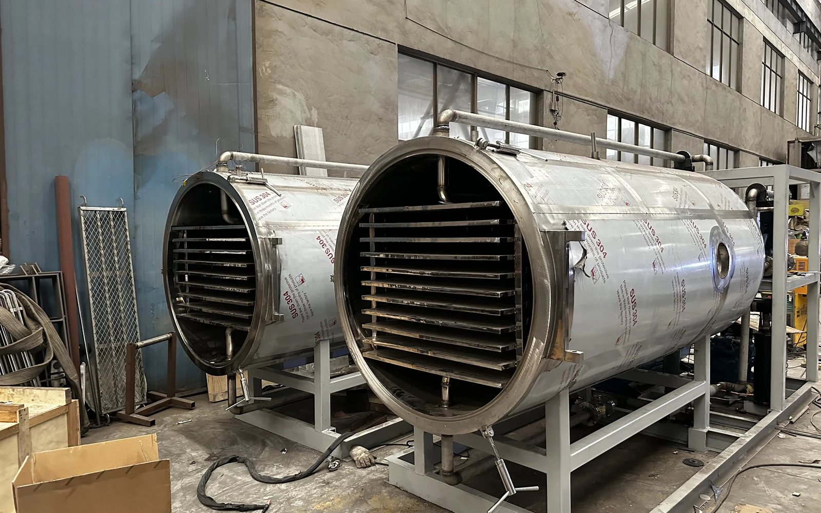
Plan food preparation, tray loading, pre-freezing, vacuum freeze drying, unloading, protective packaging, utilities and project acceptance.
Pharmaceutical & Biotech Freeze Drying
Plan lyophilization for peptides, vaccines and sterile injectables: vial formats, capping, sterile boundary and validation evidence on one project basis.
Pharmaceutical Freeze Dryer Procurement Checklist
A buyer checklist for lyophilizers: product basis, vial format, capping, 316L and CIP/SIP, data integrity, DQ/IQ/OQ/PQ and contract acceptance.